Getting a building permit can feel complicated, but it all starts with the right paperwork. This guide breaks down the 10 essential construction drawings for a building permit that you'll need. We will cover everything from the big picture site plan to detailed structural and electrical layouts, ensuring you have a clear roadmap for your application. By understanding what each drawing shows and why it's important, you can prepare a complete and accurate submission to avoid delays.
Embarking on a new construction or renovation project is an exciting venture. However, before a single nail is hammered, you must navigate the crucial step of obtaining a building permit. At the heart of this process lies a comprehensive set of documents: your construction drawings for a building permit. These drawings are more than just sketches; they are the detailed language you use to communicate your project's vision, safety, and compliance to local authorities.
This article will serve as your detailed guide to the essential drawings required. We will demystify the world of architectural plans, structural diagrams, and utility layouts. Our goal is to equip you, whether you're a homeowner, a budding developer, or a contractor, with the knowledge to assemble a permit application that is thorough, professional, and ready for approval. We’ll explore each of the 10 critical drawings, explaining its purpose and the key information it must contain.
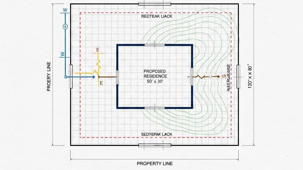
The site plan is the master document that shows your entire property from above. It provides a comprehensive overview of the project in relation to its surroundings. This drawing is crucial because it gives the permit office a clear picture of how your proposed construction fits within the existing landscape and adheres to zoning regulations.
A detailed site plan must include:
Property lines and dimensions.
The location of the proposed structure and any existing buildings.
Distances from the building to property boundaries (setbacks).
Locations of driveways, walkways, and parking areas.
Easements, public utilities, and any topographical features like slopes or trees.
A north arrow to orient the viewer.
Think of it as the foundational map upon which all other plans are built. An accurate site plan prevents potential issues with neighbors, ensures compliance with local land use rules, and is often the first drawing a plan checker will review.
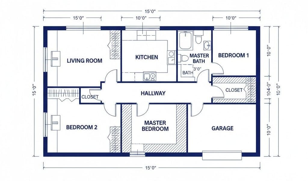
If the site plan is the overview, floor plans are the detailed interior story, one level at a time. These drawings illustrate the layout of each floor of the building as if you sliced it horizontally and looked down. They are fundamental for showing how the space will be used and for ensuring it meets safety and accessibility standards.
For a complete set of construction permit drawings, you need a separate floor plan for each level, including basements and lofts. Each plan should clearly show:
The dimensions and layout of all rooms.
The location and size of walls, doors, and windows.
Staircases, closets, and built-in fixtures.
Room names (e.g., Bedroom, Kitchen, Living Room).
Locations of plumbing fixtures and major appliances.
These plans are essential for verifying compliance with building codes related to room sizes, egress (exit routes), and ventilation.
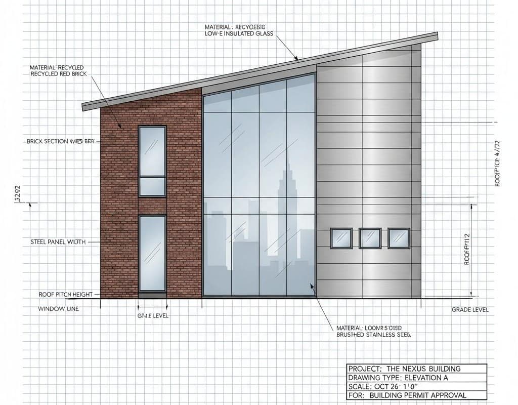
While floor plans show the inside, elevation drawings show the outside. They are 2D representations of each side of the building (front, rear, left, and right). These drawings are vital for demonstrating the building's aesthetic, the materials used, and its overall height and scale.
Key details to include in elevation drawings are:
Exterior finishing materials (e.g., brick, siding, stucco).
The style and placement of windows and doors.
Roof shape, pitch, and materials.
Porches, decks, and balconies.
Finished ground level and floor heights.
Elevations help the planning department ensure your project aligns with neighborhood character and meets any design guidelines or height restrictions.
Section drawings provide a view as if you've cut through the building vertically. They are incredibly important for showing how the structure is put together from the foundation to the roof. These drawings reveal details that aren't visible in floor plans or elevations, making them essential for verifying structural integrity and code compliance.
A typical building section will show:
Foundation and footing details.
Wall and roof construction assemblies.
Floor-to-ceiling heights.
Stair construction and headroom clearance.
Insulation details and vapor barriers.
These are some of the most technical construction drawings for building permit applications, offering a deep dive into the project's construction methods and materials.
The specific drawings needed can vary slightly by jurisdiction, but a standard set is required for nearly any significant project. These documents work together to provide a complete picture of what you plan to build and how you plan to build it, ensuring it is safe, functional, and compliant with all regulations.
Here is a summary table of the core drawing types:
Drawing Type | Purpose | Key Information Included |
Site Plan | Shows the entire property and project context. | Property lines, building location, setbacks, utilities. |
Floor Plans | Details the layout of each floor. | Room dimensions, walls, doors, windows, fixtures. |
Elevations | Displays the building's exterior from all sides. | Materials, heights, window/door styles, roof pitch. |
Sections | Reveals the internal construction assembly. | Foundation, wall/roof structure, insulation, heights. |
Foundation Plan | Details the structural base of the building. | Footings, foundation walls, slabs, support columns. |
Framing Plans | Outlines the building's structural skeleton. | Joists, beams, rafters, trusses, columns. |
Structural Details | Provides close-ups of critical connections. | Beam connections, anchor bolts, reinforcement. |
Electrical Plan | Maps out the electrical system. | Outlets, switches, lights, panel box, circuits. |
Plumbing Plan | Shows the water supply and drainage systems. | Pipes, fixtures, drains, vents, water heater. |
HVAC Plan | Lays out the heating and cooling systems. | Ductwork, vents, furnace, air conditioner unit. |
The foundation plan is a specialized drawing that details the structural base supporting the entire building. It's a top-down view of the foundation, showing how it will be constructed to safely transfer the building's load to the ground. Accuracy here is non-negotiable, as a faulty foundation can compromise the entire structure.
This plan must specify:
The type of foundation (e.g., slab-on-grade, crawl space, or full basement).
The dimensions and thickness of footings and foundation walls.
The location of support columns, piers, and reinforcement steel (rebar).
Details for anchor bolts that connect the framing to the foundation.
A soil report from a geotechnical engineer is often required alongside the foundation plan to confirm that the design is appropriate for the ground conditions on your site.
Framing plans outline the "bones" of the building. They detail the size, spacing, and direction of all structural wood or steel members, such as joists, beams, rafters, and columns. A floor framing plan shows how the floor will be built, while a roof framing plan details the roof structure.
These plans are critical for the structural engineer and the building inspector. They must show:
The size and type of lumber or steel to be used.
The spacing between framing members (e.g., "16 inches on center").
The location and size of headers over doors and windows.
Details for any engineered components like trusses or laminated veneer lumber (LVL) beams.
Clear framing plans ensure the building will be strong enough to withstand loads from snow, wind, and daily use, as dictated by building codes.
While framing plans show the overall skeleton, structural detail drawings zoom in on the specific connections that hold it all together. These are large-scale drawings of critical junctions, ensuring that every piece is joined in a way that guarantees structural integrity.
Examples of common structural details include:
How beams connect to columns or posts.
How roof rafters attach to walls.
Details of reinforcement in concrete footings.
Specifications for shear walls designed to resist lateral forces like wind or earthquakes.
These details are often provided by a structural engineer and are mandatory for any project that involves more than simple, conventional framing. They prove to the inspector that every connection is designed to be safe and robust.
The electrical plan is a type of floor plan overlay that shows the location of all electrical components. Safety is the primary concern here, as faulty electrical work is a major fire hazard. A clear electrical plan ensures that the system is designed to meet the National Electrical Code (NEC) and local requirements.
Your electrical plan must include symbols for:
Outlets (receptacles).
Switches and their corresponding light fixtures.
The main electrical panel (breaker box).
Special-purpose outlets for large appliances (e.g., stove, dryer).
Smoke detectors and carbon monoxide detectors.
The plan may also include a schedule listing circuit information, ensuring the system isn't overloaded.
Similar to the electrical plan, the plumbing plan details the location of all pipes and fixtures for both water supply and drainage. This drawing ensures that the system is designed for efficiency and sanitation, preventing issues like leaks, poor water pressure, and sewer gas backflow.
A complete plumbing plan shows:
Hot and cold water supply lines.
Drain, waste, and vent (DWV) pipes.
The location of all fixtures: sinks, toilets, showers, tubs, and the water heater.
Pipe sizes and materials.
Connection points to the municipal water supply and sewer system (or septic system).
Proper plumbing design is crucial for public health and is closely reviewed during the permit process.
The HVAC (Heating, Ventilation, and Air Conditioning) plan outlines how the building will be heated, cooled, and ventilated. A well-designed HVAC system provides comfort, energy efficiency, and healthy indoor air quality.
The HVAC plan should detail:
The location of the furnace, air conditioner, or heat pump.
The layout of ductwork for forced-air systems.
The placement of supply and return air vents or registers.
Ventilation details, such as exhaust fans in bathrooms and kitchens.
Thermostat locations.
The plan may also include calculations to show the system is appropriately sized for the building, which is a key part of modern energy efficiency standards.
Securing a building permit is a milestone that transforms your vision into an actionable project. The key to a smooth approval process is a complete and accurate set of construction drawings for a building permit. Each of the ten drawings we've discussed serves a distinct, vital purpose—from the macro view of the site plan to the micro-details of a structural connection. Together, they form a cohesive narrative that proves your project is well-planned, safe, and compliant. Investing the time and resources to get these drawings right from the start is the most effective way to prevent costly delays and ensure your project begins on solid ground.
If you are looking to deepen your understanding of engineering principles and explore more detailed guides, you can find a wealth of knowledge at engides.com.
Permits Require Detail: A building permit application is built on a foundation of detailed construction drawings.
Ten Core Drawings: A complete set typically includes a site plan, floor plans, elevations, sections, and plans for the foundation, framing, electrical, plumbing, and HVAC systems, plus structural details.
Drawings Tell a Story: Each drawing provides a specific piece of information, and together they offer a comprehensive view of the project's design, safety, and compliance.
Compliance is Key: The primary purpose of these drawings is to demonstrate that your project adheres to local zoning laws and national building, electrical, and energy codes.
Invest Upfront: A thorough and professional set of permit drawings vs construction drawings (which are often the same at this stage) saves time and money by preventing rejections and requests for more information from the permit office.